Insertion
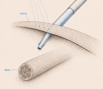
Insert the needle under ultrasound guidance.
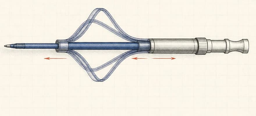
Joint masters thesis: Developed and tested a catheter-anchoring concept designed to keep a nerve-block catheter within 2 mm of its intended position, without disrupting the anesthesiologists existing workflow or introducing additional patient risk.
How might an anchor resist movement during use while still allowing intended removal?
JOINT MSc THESIS · FIVE MONTHS · EXPLORATORY / NON-CLINICAL
THE PROBLEM WAS MOVEMENT WITHIN A PROCEDURE.
Catheter behaviour depended on insertion, ultrasound guidance, needle removal, activation, infusion and intended removal—not one isolated mechanism state.
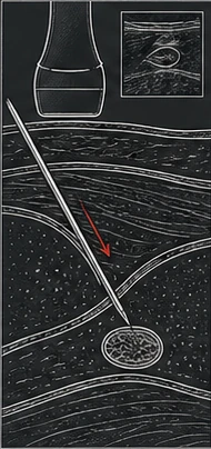
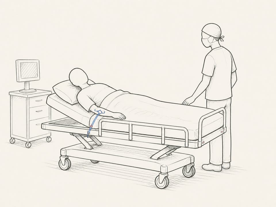
Insert the needle under ultrasound guidance.
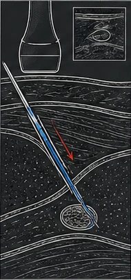
Advance the catheter near the target nerve.
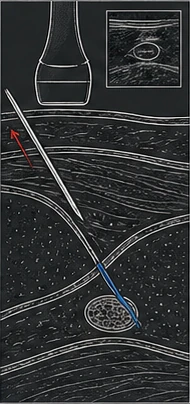
Withdraw the needle, leaving the catheter in place.
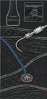
Deploy the anchor and connect the infusion line.
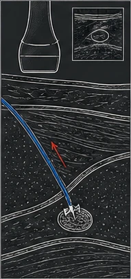
Retract the catheter and anchor when treatment is complete.
The mechanism had to work inside the full clinical workflow.
Insertion, ultrasound guidance, needle removal and intended removal could not be designed separately.
The evidence was synthesized into one reviewable CPNB procedure storyboard.
KEEP OBSERVATIONS, SOURCE STORYBOARDS AND EXPLANATORY FLOWS DISTINCT.
The team combined procedure observations, clinician conversations, a jelly insertion exercise, literature and benchmarking into a shared view of the problem.
Separating what was observed from what was later synthesized keeps the clinical context useful without converting four single-shot blocks into evidence for an anchor procedure that was not observed.
Flower catheter · anchor activation included
Bring the patient into the anaesthetic room and explain the procedure.
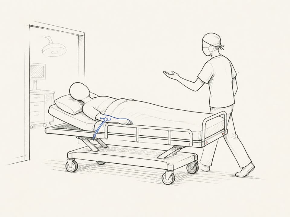
Prepare the ultrasound device and brief the patient.
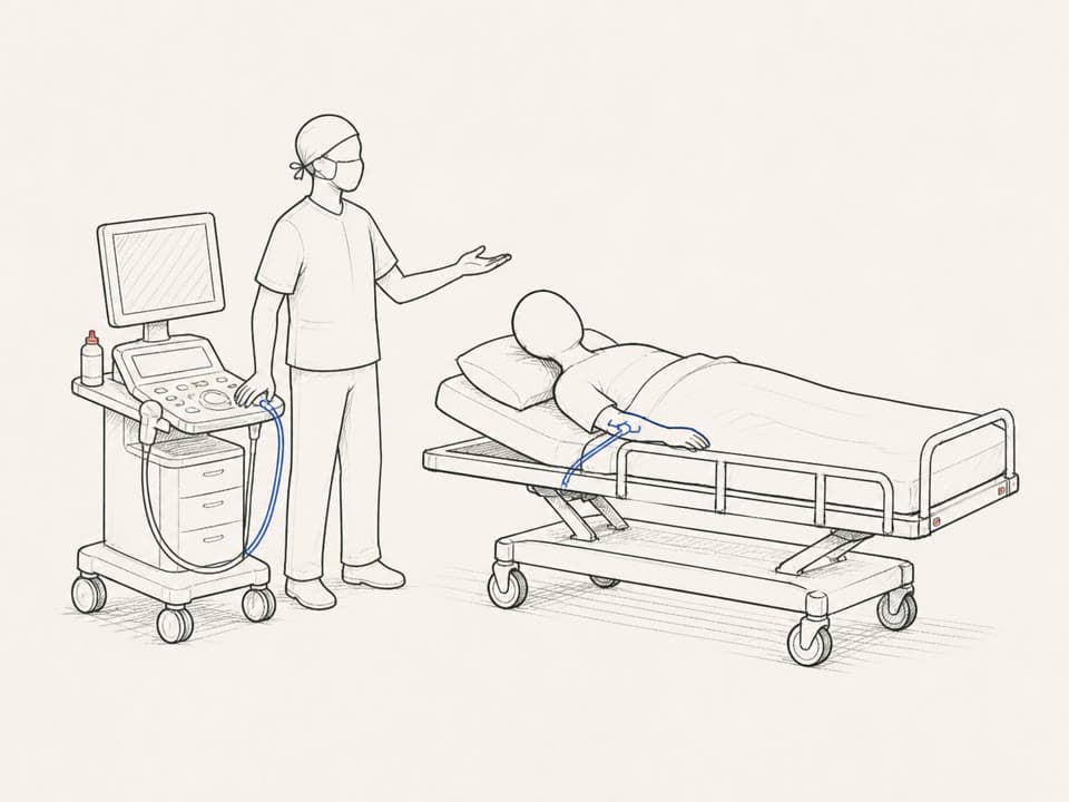
Prepare the anaesthetic and sterile equipment.
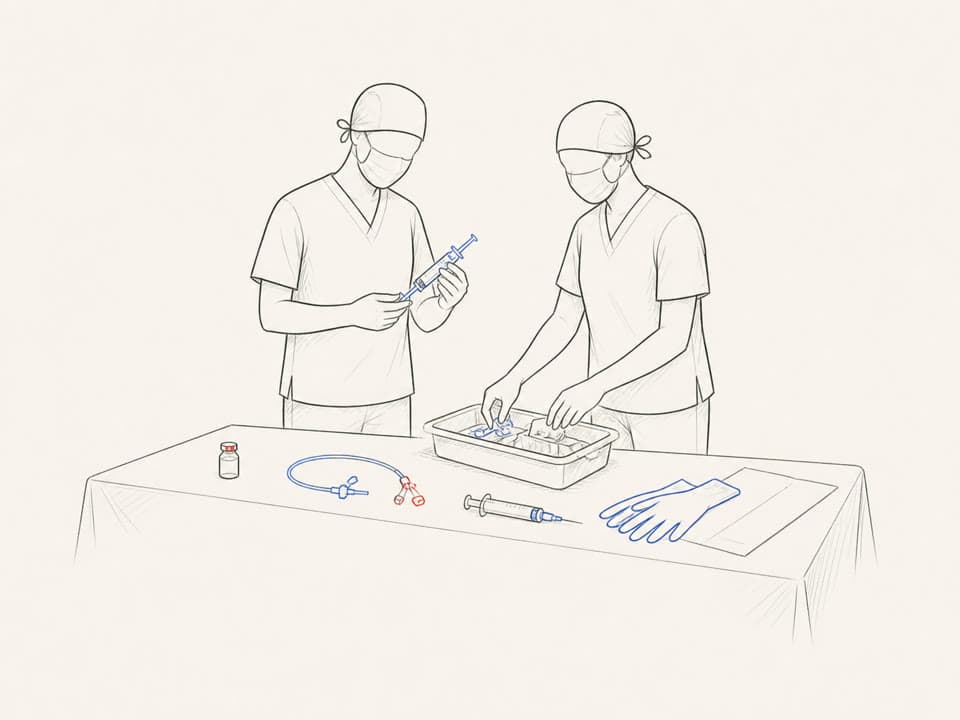
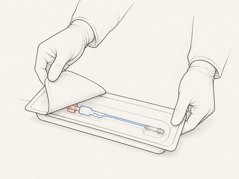
Remove the Flower catheter from its sterile package.
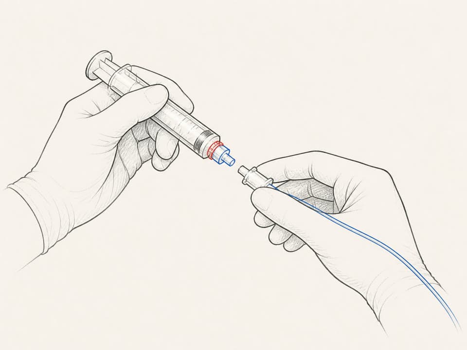
Connect the backend to the tube and syringe.
Apply gel and identify the target nerve with ultrasound.
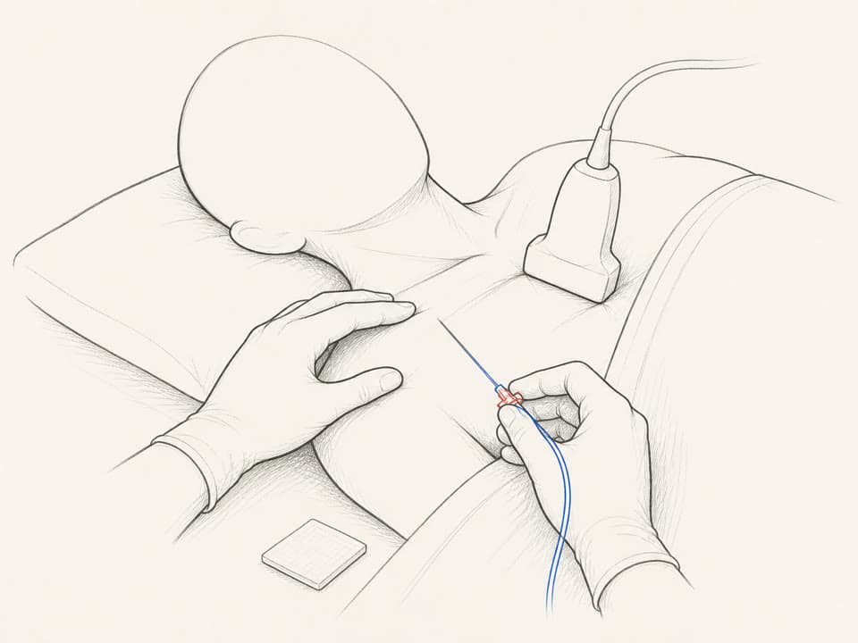
Clean the site and insert the needle with the outer catheter.
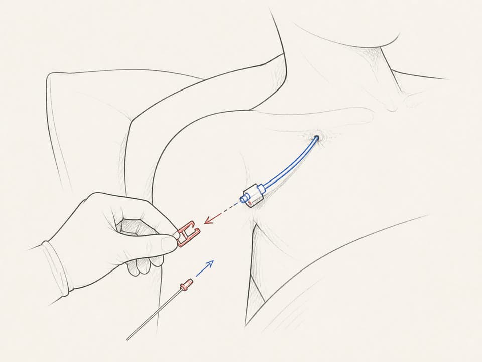
Unlock the needle and withdraw it while holding the catheter steady.
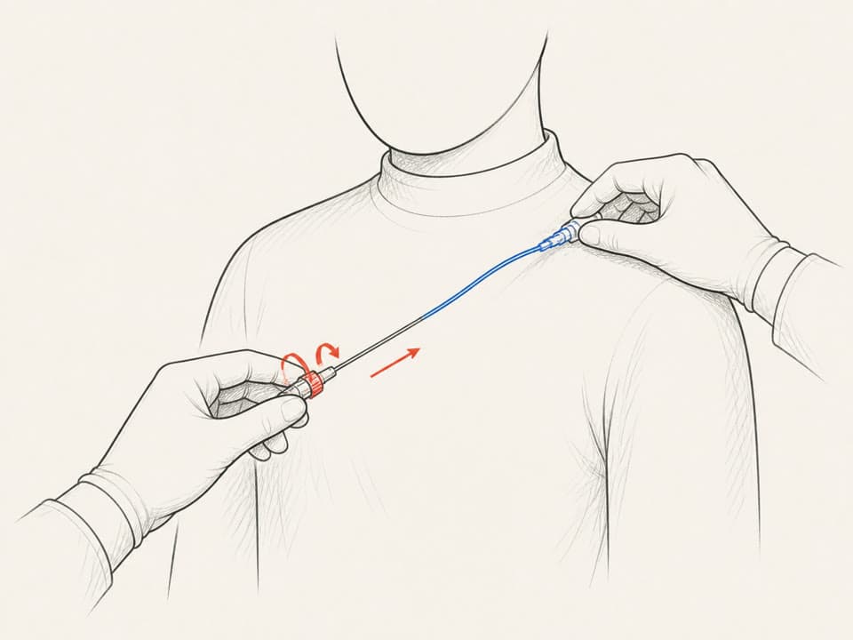
Push the clip to deploy the Flower anchor.
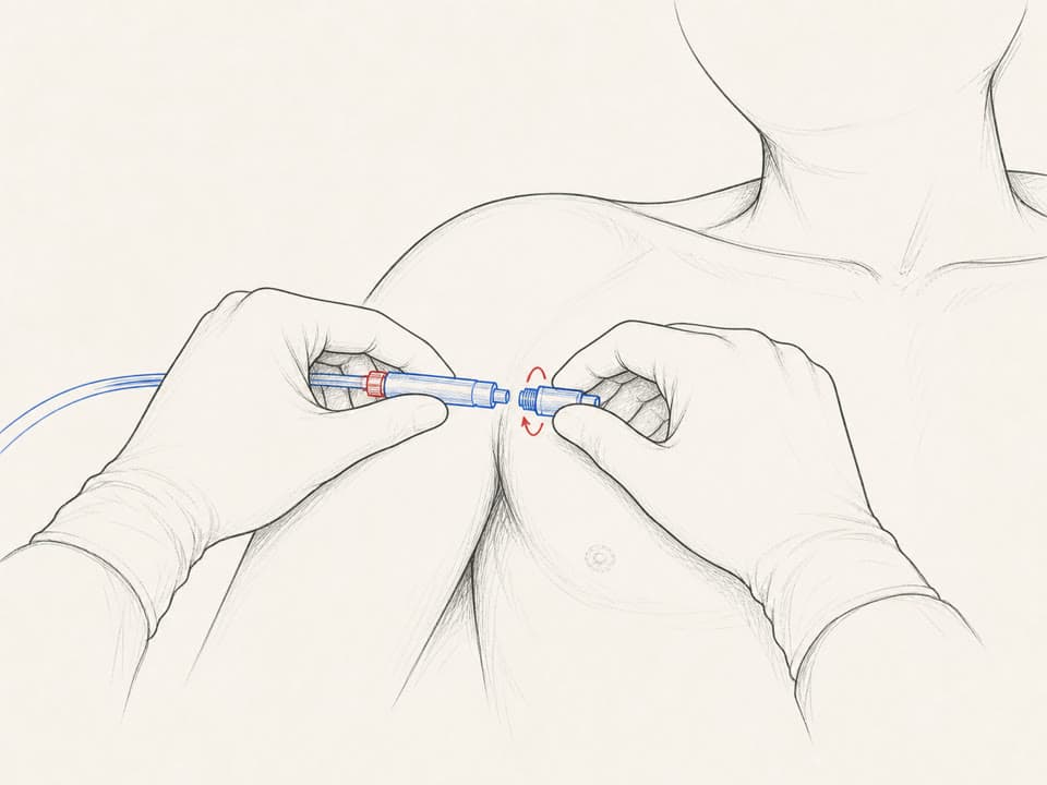
Connect the anaesthetic supply tube to the catheter.
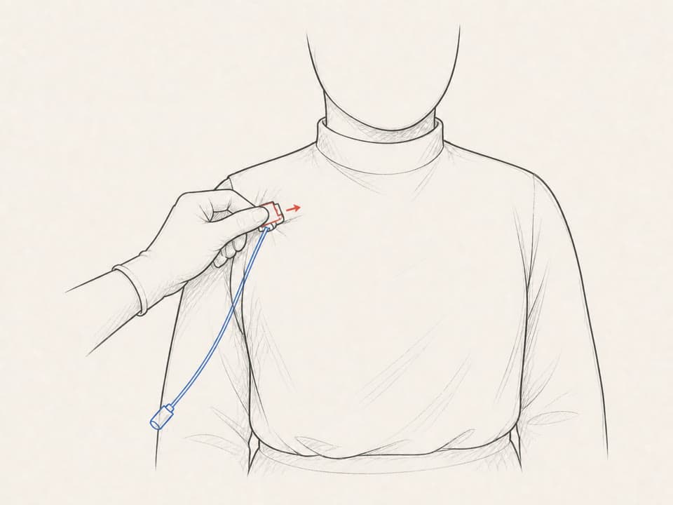
Observe the patient and check the efficacy of the nerve block.
Swipe, scroll or use the arrows to follow the sequence.
MOVE FROM PRIOR EVIDENCE TO FUNCTIONS, FOCUS AND SPECIFICATION.
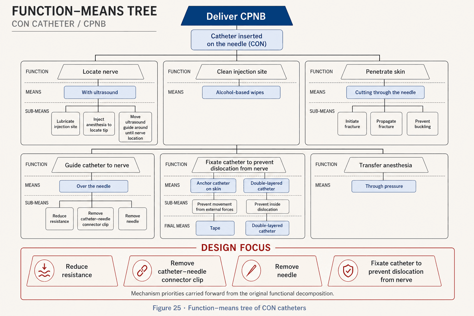
Function-means trees isolated four critical functions. After doctor discussions, catheter fixation became the primary development focus.
A requirement was treated as essential for viability; a criterion was a desirable attribute that could improve the product without being strictly necessary.
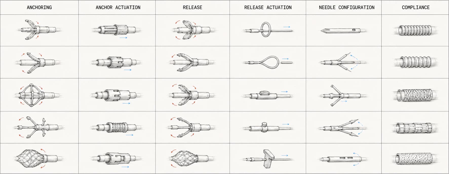
OPEN THE SOLUTION SPACE BEFORE EVALUATING IT.
Four ideation approaches fed a morphology chart and a catalogue of 25 catheter concepts.
Breadth came before screening. These drawings record ideation—not proof that the mechanisms would work.
Ideation methods



Idea catalogue
25 contextualized catheter concepts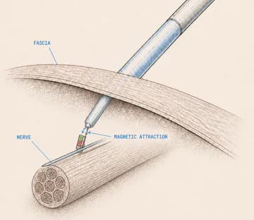
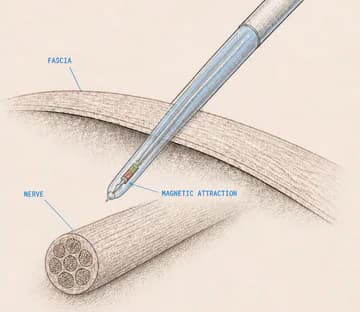
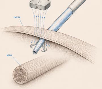
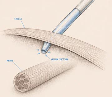
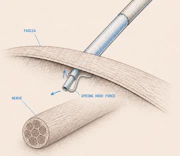
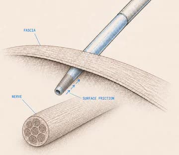
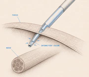
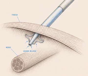
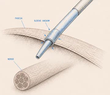
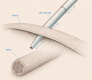
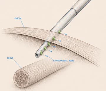
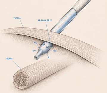
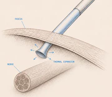
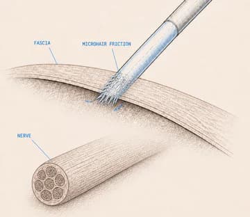
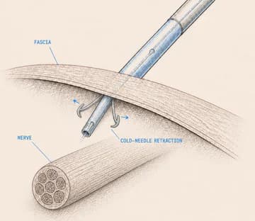
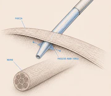
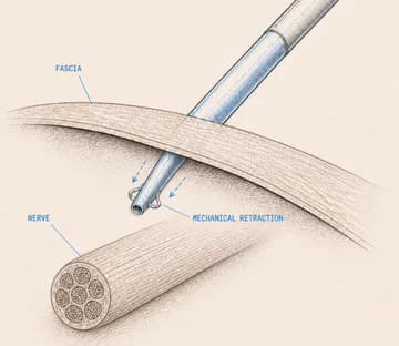
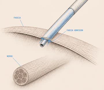
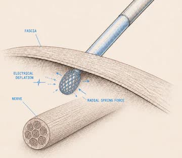
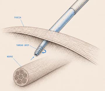
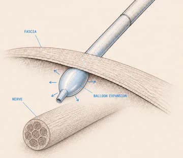
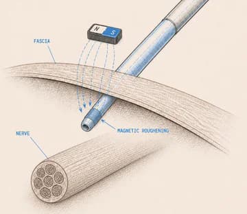
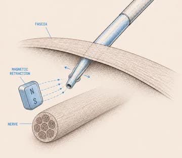
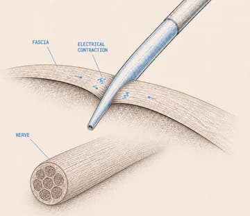
ELIMINATE WHAT CANNOT BE BUILT BEFORE ASKING WHAT PEOPLE PREFER.
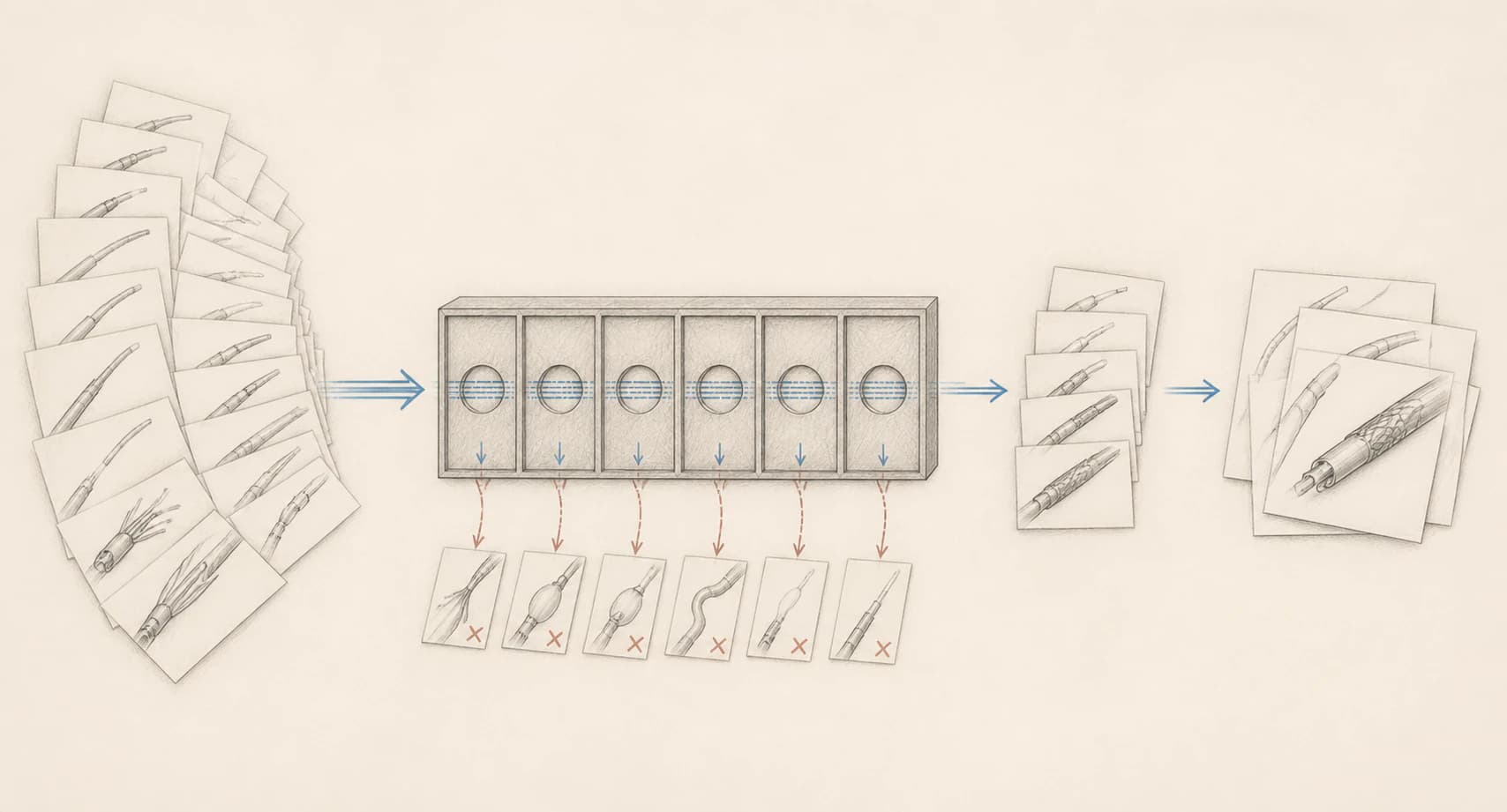
Six non-negotiable engineering checks removed 14 of the 25 concepts. Combining and developing the survivors then produced seven candidates for stakeholder evaluation.
With 25 directions on the table, the team switched from divergence to elimination. Every concept had to pass the same six engineering checks: manufacturability, independent anesthesia flow, confidence in the anchoring principle, feasibility at a 1 mm diameter, material availability and passive anchoring without continuous energy.
The screen removed 14 concepts and left 11 viable directions. Only after that gate were related ideas combined and developed into seven candidates for stakeholder review. This was a decision-making step—not evidence that any surviving mechanism had already been validated.
Six hard criteria
Mass-producible with current manufacturing technologies
Anesthesia flow remains independent of anchoring
Certainty that the anchoring principle works
Feasible to produce at 1 mm diameter
Required materials available at the necessary scale
No active energy required to remain anchored
STAKEHOLDER RANKING ALONE DID NOT RESOLVE THE DECISION.
Seven developed concepts were reviewed through doctor, manufacturing-expert and supervisor lenses, then compared with a weighted Pugh method.
Different stakeholder rankings made a second comparison method necessary. Flower and Cone moved forward because the decision process selected them—not because either had already demonstrated a validated performance result.
Review lensesDoctors · Manufacturing expert · Supervisor
| Weighted Pugh criteria | 09Screw | 15Vacuum deactivated anchor | 16Magnetic deactivated anchor | 19FlowerSelected | 22ConeSelected | 23String Folder | 25Sponge |
|---|---|---|---|---|---|---|---|
1Stakeholder rankingWeight 6 | 6 | 5 | 6 | 9 | 8 | 5 | 4 |
2Potential to transition from CTN to CONWeight 5 | 4 | 5 | 5 | 8 | 9 | 4 | 3 |
3ManufacturabilityWeight 8 | 7 | 4 | 5 | 7 | 8 | 5 | 4 |
4Anchoring-size potentialWeight 10 | 6 | 4 | 5 | 8 | 8 | 4 | 3 |
| Weighted score (Σ) | 172 | 127 | 151 | 230 | 237 | 130 | 101 |
LET PHYSICAL FAILURE OVERRULE A PROMISING PAPER CONCEPT.
The first prototype phase used scaled-up anchor-tip models, simple available materials and quick processes rather than attempting complete catheters.
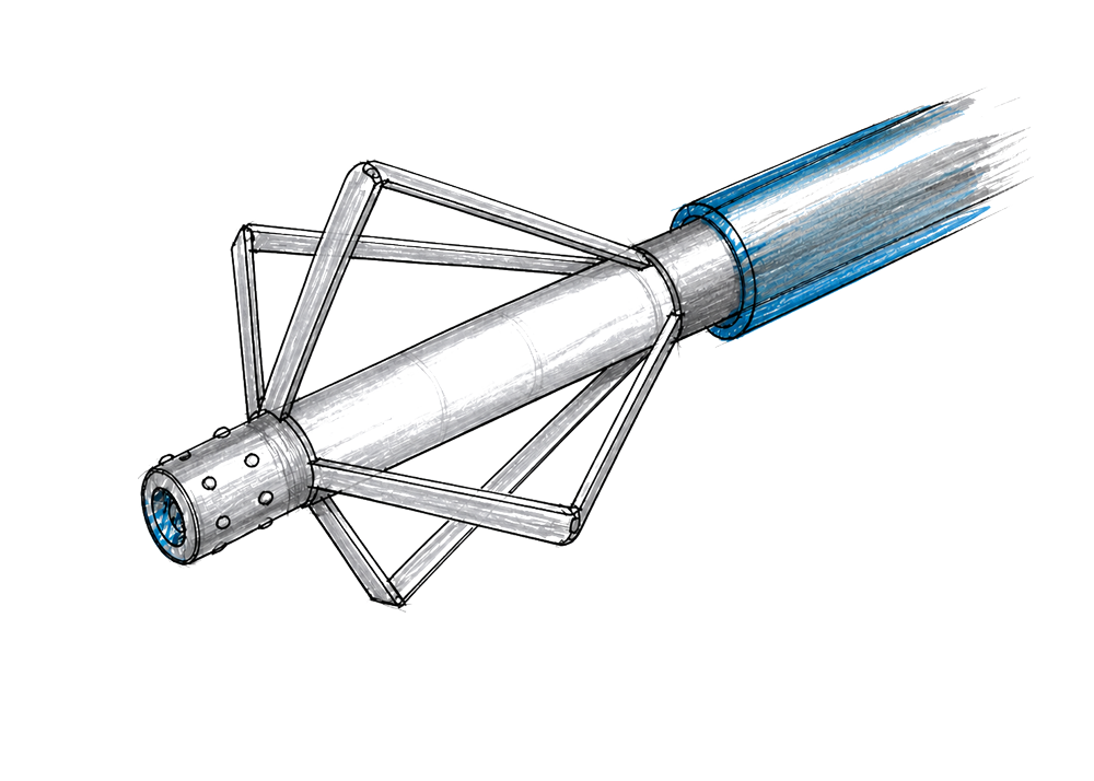
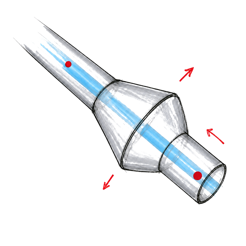
Cone stopped within the project scope after demoulding and folding failures. Flower earned the next development cycle because the principle model demonstrated the intended deploy-and-release motion at enlarged scale.
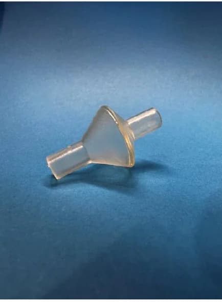
Silicone dip moulding failed during demoulding and was too soft for the anticipated snap behaviour. The Flexible 80A SLA version could not fold flush or reach the required minimum diameter.
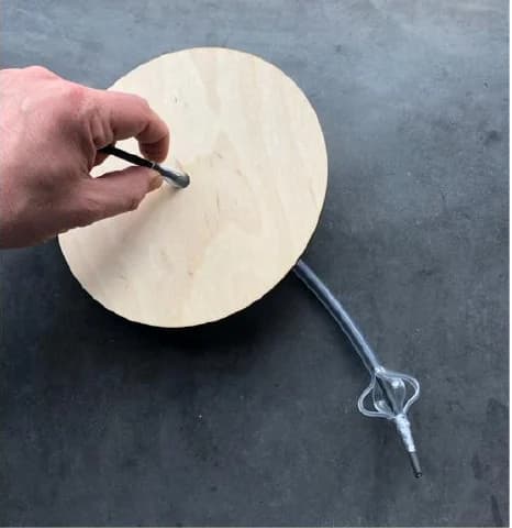
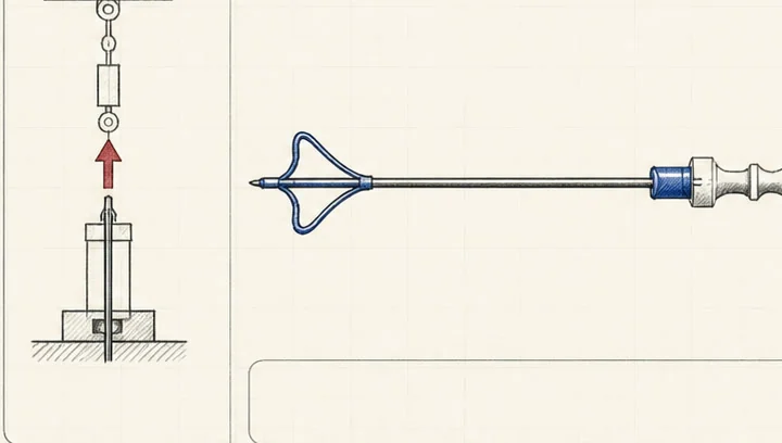
A PVC tube and inner cable were joined at the tip. Relative movement opened the longitudinal slots and the folding structure deployed as intended.
MOVE FROM AN ENLARGED PRINCIPLE TO CATHETER-SCALE TUBING.
Doctor-provided catheters, spare tubing and manufacturer samples exposed cutting, rotation and support problems that the next fixtures had to control.
The manufacturing problem became part of the mechanism problem: a cut that wandered changed the rib geometry, and a tube without internal support could not be cut consistently enough for the next test stage.
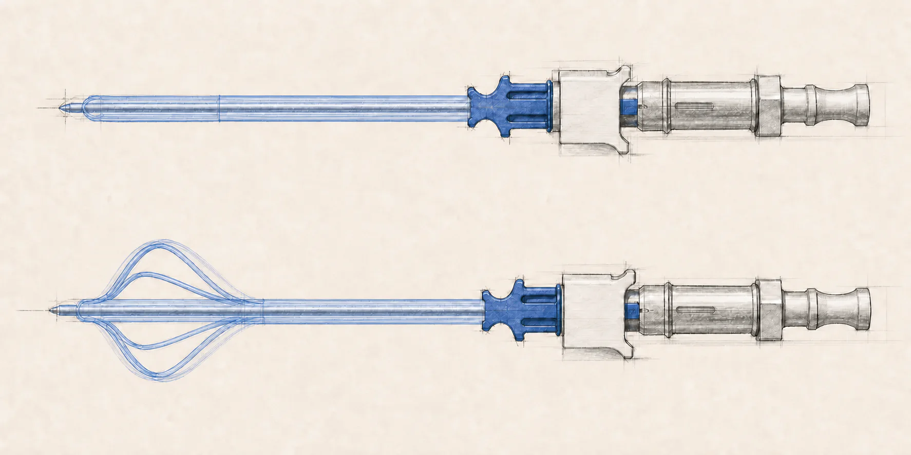
Test doctor-provided catheters, spare tubing and manufacturer samples.
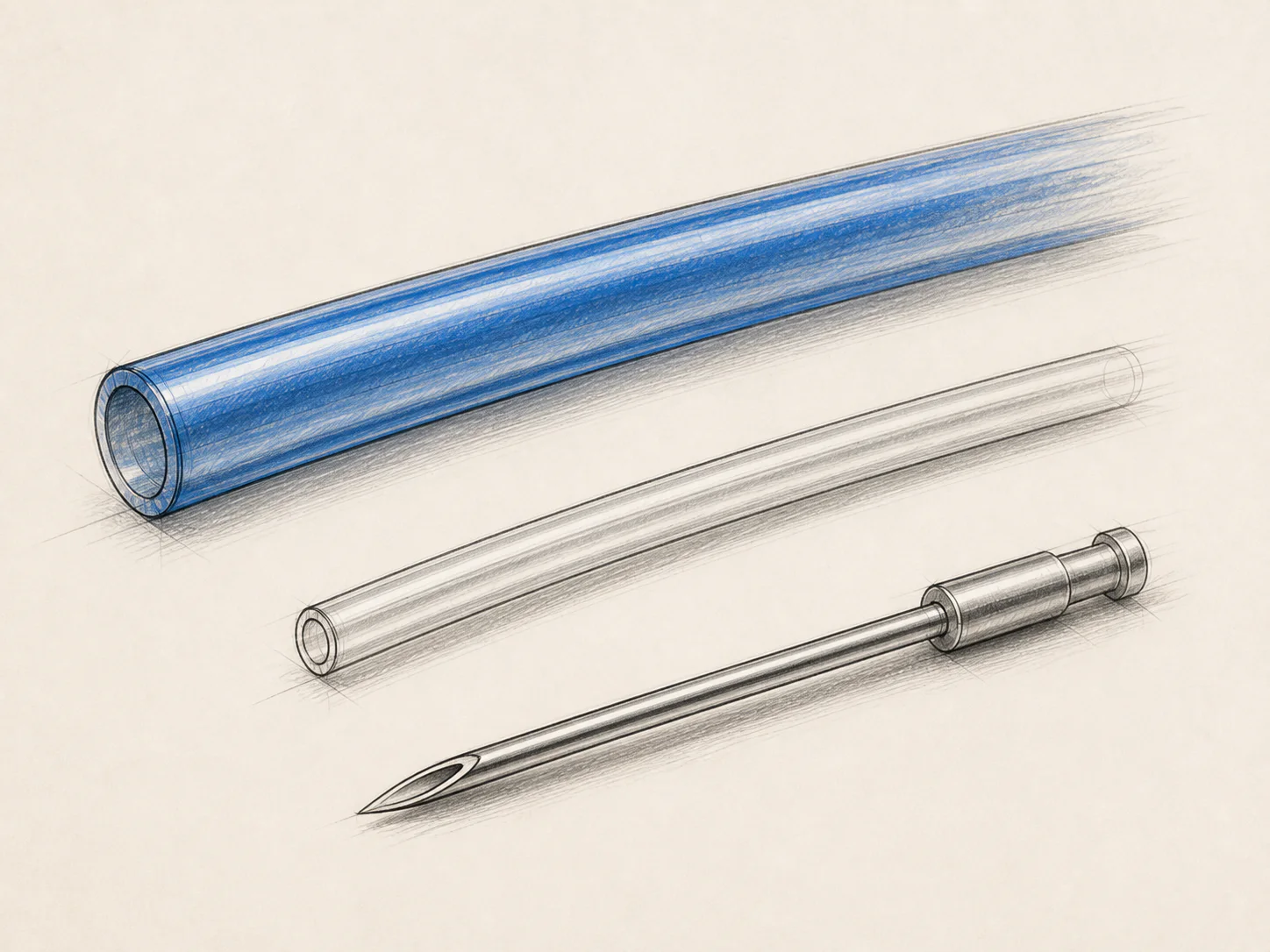
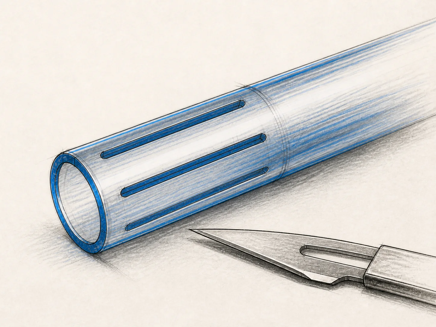
Razor and scalpel cuts were possible but drifted from the tube centre and produced uneven slits.
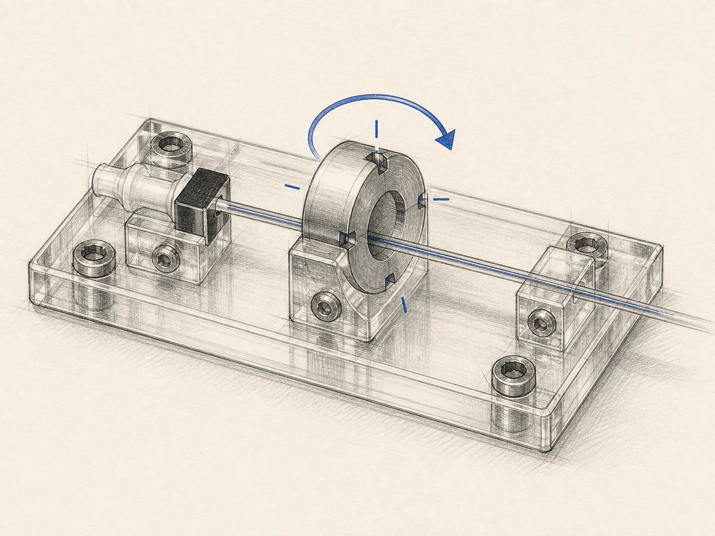
A fixture was needed to rotate the tube through four defined 90-degree positions.
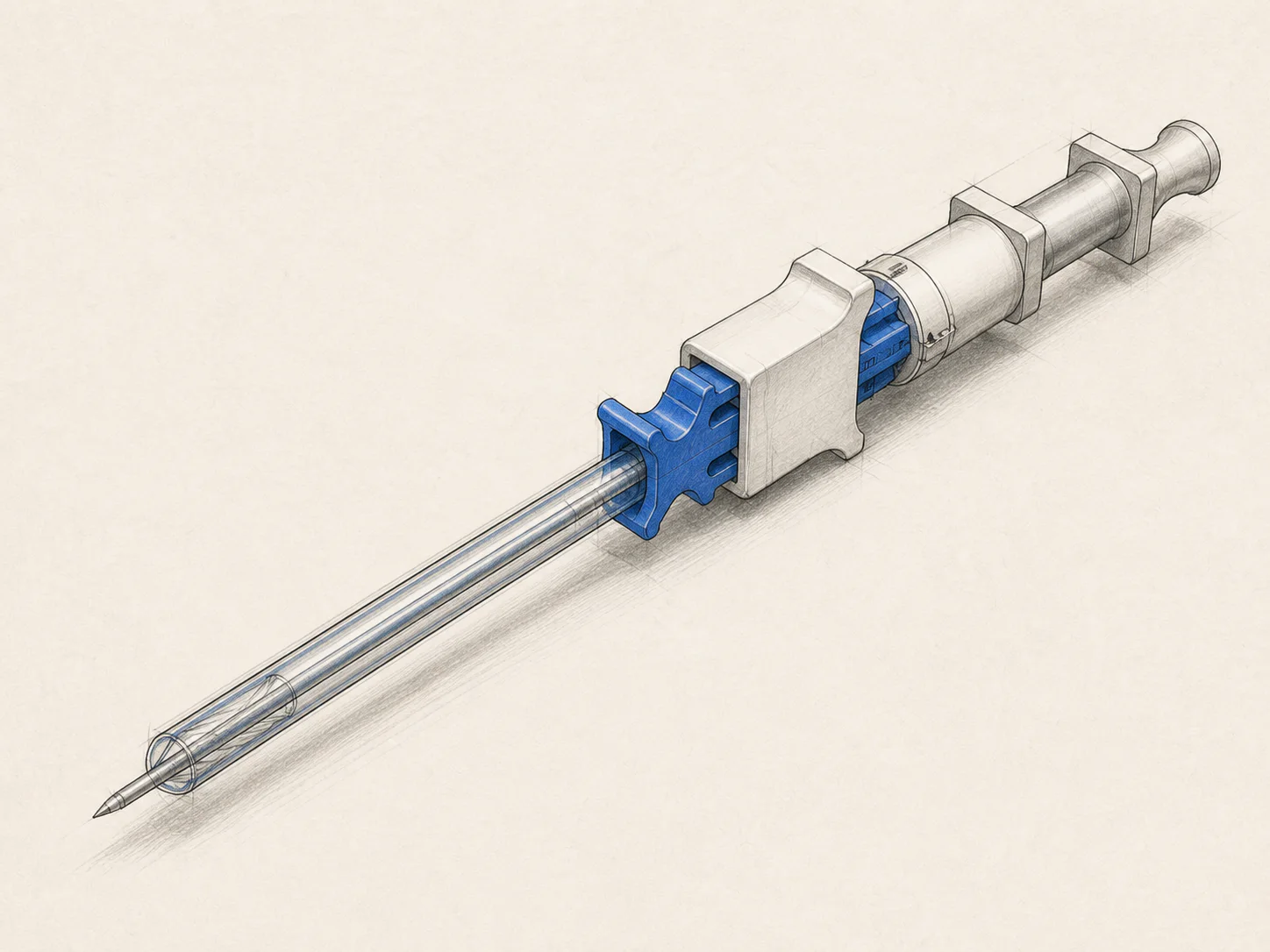
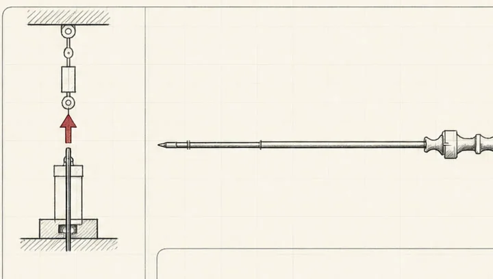
The tubing needed internal support during cutting, so it was fed over a needle.
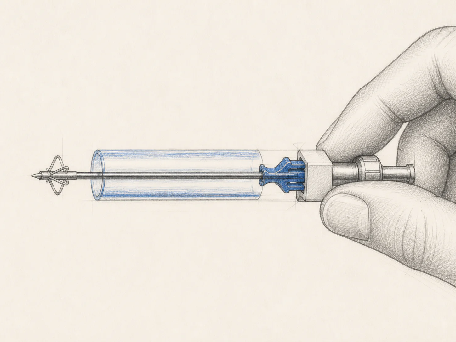
Doctors favored catheter on the needle due to easier control.
WHEN THE SETUP CHANGES THE RESULT, THE SETUP BECOMES PART OF THE DESIGN.
The third prototype phase moved from hand-pulled gelatin tests to a motorized rig and revised locking system, so the anchor could be compared under more defined conditions.
Pull speed varied with counterforce, and the shallow 4 × 4 cm gelatin specimen left too little material above the anchor for the intended pull-out setup.
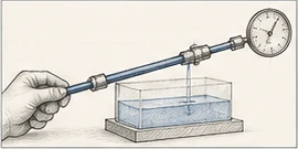
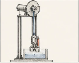
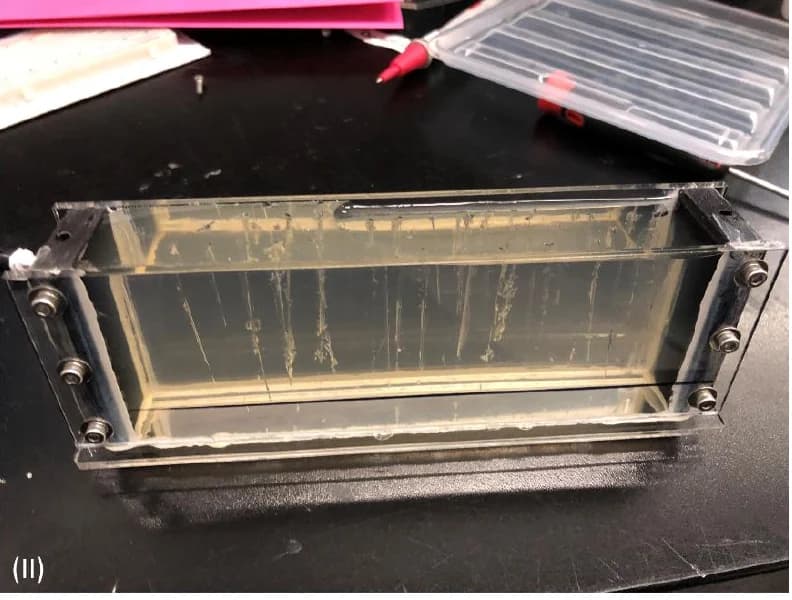
A geared rig moved the Newton meter along one defined axis, while a deeper holder constrained specimen movement and enabled observation through acrylic windows.
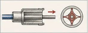
The one-way clip loaded only the inner tube and progressively activated the anchor, creating an unrepresentative pull-out load case.
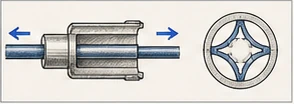
The revised clip held the inner and outer tubes relative to one another in both deployed and undeployed positions.
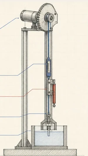
The V2 rig reduced important sources of handheld variation. Its measured 6.5 mm/s pull speed is a rig setting—not the separate 6.5 N maximum recorded later in one ex-vivo session.
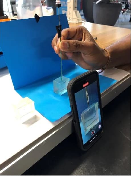
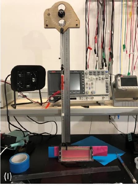
The geared line moved the Newton meter vertically instead of relying on a hand-pulled path.
The acrylic holder constrained the gelatin and made the pull-out path observable.
More-controlled mechanics improved comparison, but did not turn the setup into a validated test standard.
LET THE METHOD, RESULT AND LIMITS TRAVEL TOGETHER.
The Flower moved through a more-controlled gelatin comparison before one final ex-vivo tissue session with doctors at Hillerød Hospital.
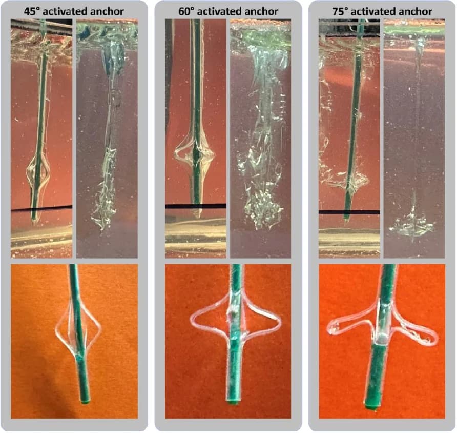
Two 12 mm-cut catheters—one beveled and one unbeveled—were each used at 45°, 60° and 75°. Three pull measurements were recorded per tip/angle condition using two catheters total. These were not independent specimens and do not establish repeatability.
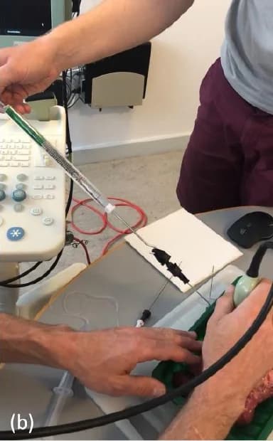
The 60° and 75° anchors were compared with a straight control and Pajunk CON under ultrasound observation.
The largest recorded value came from the 60° anchor at complete pull-out in this documented setup.
What the results support
12 mm anchor · 60° deployment
Maximum recorded in this setup
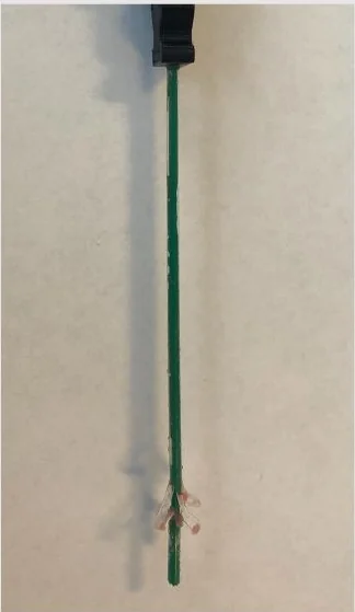
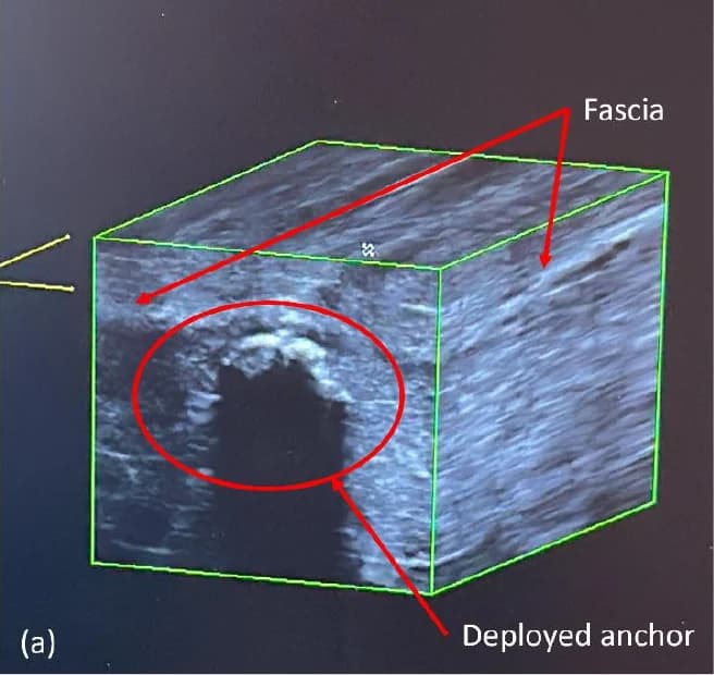
The anchor deployed beneath fascia under ultrasound observation. Complete pull-out occurred suddenly; the anchor was deformed and partly broken afterward.
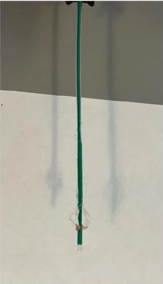
Real-project photographs document the specimens, handheld Newton meters and ultrasound observation. The deeper record keeps the unmatched 75° condition, control gliding, failures and unresolved tissue interaction visible beside the four recorded maxima.
| Condition | Maximum | What was documented |
|---|---|---|
| 12 mm anchor · 60° | 6.5 N | The anchor was behind fascia. Complete pull-out occurred suddenly; the anchor was deformed and partly broken afterward. |
| 12 mm anchor · 75° | 4.5 N | This condition was placed in flesh, required several insertion attempts and pre-cutting, and began activating during insertion. |
| Straight control | 1.5 N | Behind fascia; the catheter began gliding at about 1 N before reaching its maximum. |
| Pajunk CON | 1.5 N | Behind fascia; the catheter began gliding at about 1 N before reaching its maximum. |
Additional limits: the 45° / 9 mm tip-glue connection failed; possible tissue ripping or cutting remained unresolved; and the gelatin pulls used two catheters total, not independent specimens.
Turn observations, clinician input, a jelly exercise, literature and benchmarking into a reviewable problem sequence.
Open the solution space, apply hard criteria, compare stakeholder preferences and let physical failures change direction.
Move from scaled principles to catheter-scale cuts, concentric tubes, locks and dedicated fixtures.
Make variables more controlled while keeping the result, setup and unresolved confounds together.